
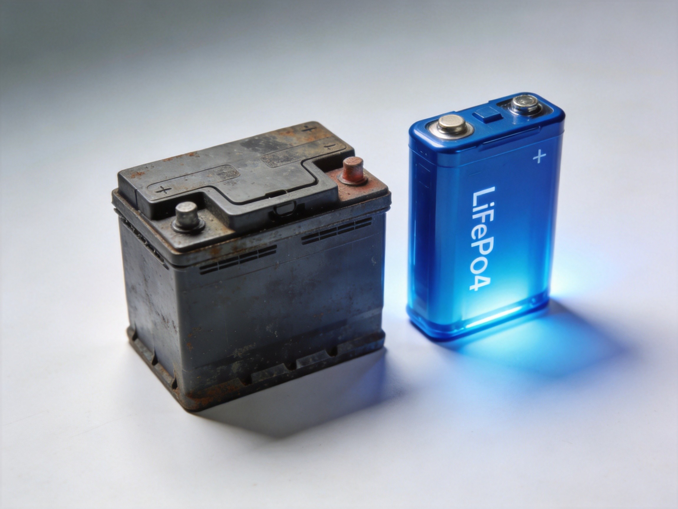
A battery management system, or BMS, is the electronic controller that keeps every LiFePO4 cell in a storage pack inside its safe voltage, current and temperature limits. Without one, even a brand-new 51.2V solar battery can be damaged in a single overcharge or deep-discharge event, which is why every CMJ Solar Apollo, Ares and Athena battery ships with a built-in BMS.
What Is a Battery Management System?
A 51.2V LiFePO4 battery is not one cell. It is 16 prismatic cells in series, each nominally 3.2V, and in a cabinet such as the Apollo A Series 10kWh All-in-One ESS several cell groups are paralleled to reach 200Ah and 10240Wh. The BMS is the control board mounted against the cell stack that measures each cell, drives the charge and discharge contactors, and exchanges data with the inverter.
Buyers comparing quotations sometimes treat the BMS as a generic checkbox. In practice it is the component that decides whether a battery reaches its rated cycle life or fails within two years. A well-designed BMS performs four jobs: it equalizes the cells, it interrupts dangerous current, it estimates how much energy is left and how healthy the pack is, and it communicates with the rest of the system. The following sections explain each job in engineering terms.
Cell Balancing: Passive vs Active
No two cells are identical. Manufacturing tolerance, temperature gradients inside the cabinet and different self-discharge rates cause the cells in a string to drift apart by a few millivolts every month. Because the cells are wired in series, the weakest cell dictates when charging must stop and when discharge must end. Without balancing, one cell reaches 3.65V while its neighbors sit at 3.30V, and a large share of the pack's nominal energy stays locked away.
Passive balancing is the standard in stationary storage. A resistor and a MOSFET switch are connected across each cell. When a cell reaches the top of the charge curve, the BMS bleeds its excess current as heat so the lagging cells can catch up. Typical passive balance current is 50 to 150mA. The approach is cheap, robust and perfectly adequate for solar duty, where charge cycles are long and slow at 0.1C to 0.2C.
Active balancing transfers energy from strong cells to weak ones through small transformers or switched-capacitor circuits, with conversion efficiency usually quoted around 80 to 90 percent. It wastes less energy and balances faster, but adds cost and additional failure points. For most residential and light-commercial solar cycles, passive top-balancing holds cell spread inside roughly 20 to 30mV, which is the band reputable manufacturers target. The Athena Wall-Mounted Battery Value Series 34kWh (51.2V/670Ah) with 200A BMS illustrates why this matters: across 670Ah of capacity, even a small voltage spread represents real kilowatt-hours that only disciplined balancing can recover.
Overcharge, Over-Discharge, Overcurrent and Short-Circuit Protection
The BMS is also the pack's safety relay, and four protection functions cover nearly every field failure. Overcharge protection disconnects charging when any cell reaches about 3.65V. LiFePO4 does not suffer the dramatic thermal runaway associated with cobalt chemistries, but overcharging still accelerates side reactions, raises internal pressure and shortens calendar life. Over-discharge protection cuts the load when cells fall to roughly 2.5V; left below that level for weeks, cells can develop copper dissolution and never recover their full capacity.
Overcurrent protection monitors a current shunt and opens the contactor when sustained draw exceeds the BMS rating, while short-circuit protection reacts within microseconds, typically at several times rated current. These ratings must be read together with the product datasheet: the Apollo A Series 10kWh is built around a 200A discharge path, its 6KW inverter version accepts up to 120A of MPPT charge current, and the 12KW variants accept up to 160A, so BMS, busbars and fuses are engineered as one matched set rather than isolated parts.
Temperature cutoffs complete the protection set. NTC probes on the cells and on the power switches let the BMS throttle current or open contactors when the pack runs too hot, and block charging below freezing. The low-temperature charge rule is important enough to deserve its own treatment in our article on LiFePO4 cold-weather performance and heating, and general upkeep is covered in our LiFePO4 maintenance tips.
SOC and SOH: What the Percentage on the Screen Means
State of charge, or SOC, is the percentage of energy currently available. Because the LiFePO4 voltage curve is exceptionally flat, hovering around 3.2 to 3.3V through most of its range, voltage-only fuel gauges are nearly useless. A competent BMS uses coulomb counting, integrating current in and out over time, and corrects drift each time the pack reaches a known full or empty anchor. Better implementations add temperature compensation and learn from recent cycles. SOC accuracy of roughly 2 to 5 percent on a calibrated BMS is realistic; any claim of one percent is usually marketing.
State of health, or SOH, compares the pack's current full-charge capacity with its rated capacity. A battery at 80 percent SOH after several thousand cycles is considered at end of life under most warranty frameworks. SOH cannot be measured directly; it is inferred from accumulated energy throughput, internal resistance growth and periodic capacity relearns. This is why the 5-year warranty CMJ Solar offers on its LiFePO4 systems is backed by BMS log data rather than a calendar guess, and why installers should export a BMS report before filing any warranty claim.
CAN and RS485: How the BMS Talks to the Inverter
A BMS that cannot communicate forces the battery and inverter to operate blind. The two physical layers dominating residential and commercial storage are CAN bus and RS485, the latter usually carrying the Modbus RTU protocol. CAN is fast, differential and common on modern hybrid inverters; RS485 is simpler, supports longer cable runs and remains the default in telecom and industrial cabinets.
Over these links the BMS reports pack voltage, SOC, SOH, cell temperatures, alarms and cycle count, and it sends the inverter a dynamic charge and discharge current limit. When cells are nearly full or very cold, the BMS instructs the inverter to taper charge current; when a fault trips, it commands an immediate stop. This handshake is what allows an all-in-one machine such as the Ares 15kWh All-in-One ESS with 12KW Inverter to combine dual 7500W MPPT inputs with a 200A discharge path without mismatched protection settings.
When batteries are paired with third-party inverters, protocol compatibility should be verified in writing before the order, because a hardware-only pack is limited to fixed voltage thresholds. Our 25.6V 100Ah hardware-version rack module, for example, is explicitly listed as not compatible with inverter communication and is intended for voltage-based applications, whereas the software version is built for protocol-level integration. You can compare the two approaches in the rack-mounted battery range.
Why Integration Matters Inside an All-in-One ESS
In a split system the installer separately configures battery, inverter and charger, and one wrong parameter can void a warranty. In an all-in-one ESS the manufacturer has already matched the BMS firmware to the inverter, set the LiFePO4 charge curve around 56V to 58.4V absorption, and validated the cutoffs across the full temperature window. The Ares and Apollo families run 51.2V nominal packs with 100A to 200A discharge ratings and 230V output, which shrinks the integration risk for distributors. Buyers who want the charging background can read our explanation of how MPPT charge controllers work, and the long-term reliability case is made in our LiFePO4 vs lead-acid comparison. The complete integrated lineup is catalogued under Apollo all-in-one ESS.
What B2B Buyers Should Verify on the Datasheet
Before placing a container order, ask four questions. First, what are the balance current and trigger voltage, and is balancing confirmed at the end of every charge. Second, what are the exact protection thresholds for cell high and low voltage, charge and discharge current, and temperature. Third, which communication protocols and inverter compatibility lists are supported, and can protocol documents be provided for OEM integration. Fourth, who can read and clear BMS fault logs after installation. CMJ Solar supplies these parameters from the Jiangmen factory across the Apollo, Ares, Athena and rack-mounted ranges, including OEM and ODM firmware configuration for distributors tendering utility and telecom projects. Browse the full energy-storage catalog or contact our engineering team for the BMS parameter sheet of any target model.
Frequently Asked Questions
Can a BMS be replaced or upgraded in the field? Yes on most rack and wall-mounted designs, but the replacement must match cell count, current rating and communication protocol. A generic BMS flashed with wrong thresholds is more dangerous than the old board, so replacements should use factory-supplied firmware.
Is active balancing worth paying extra for in a solar battery? For standard residential and commercial solar duty, passive balancing is usually sufficient because charging is slow and daily. Active balancing pays back mainly in high-current, fast-charge or heavily cycled commercial applications; ask the supplier for modeled energy savings rather than accepting the feature as a generic premium.
How can I confirm the BMS is actually communicating with my inverter? The inverter screen should display battery SOC, temperature and allowable charge current rather than only a fixed bus voltage. If it shows voltage alone, communication is not established. CMJ Solar verifies these screens before shipment and supports remote commissioning checks for distributors.
Need Product Recommendations?
Our team can help you select the right energy storage or solar lighting products for your project.